Throughout this guide, left is designated as the driver's side of the vehicle, and right as the passenger's side of the vehicle.
Section I: Basic Info and Preparation
Section II: Disassembly
- Disconnect Battery
- Remove Passenger Under Dash Panel
- Removing Front Seats
- Removing Center Console
- Removing Center Console (Front Section)
- Access Under Gear Shift Mechanism
- Removing Inner Door Sill (Passenger)
- Disassembling Release for Trunk Lid
- Accessing Fuse Panel
- Accessing Relay Panel
Section III: Wiring
Section IV: Reassemble
Disconnecting the Battery
![]() Note: Prior to disconnecting the battery, you should be aware of the following:
Note: Prior to disconnecting the battery, you should be aware of the following:
- It's been reported that disconnecting the battery on cars with low fuel (i.e. less than quarter tank) may cause the fuel gauge to display incorrectly.
- Wiring harness plugs of control modules or other electronic components must be (dis)connected with the ignition off. Exception: vehicles with the additional equipment M 536 (alarm siren with tilt sensor) must be disconnected with the ignition on in order to avoid triggering the alarm siren.
- If you disconnect the battery with the ignition on it may cause your airbag warning lamp to illuminate, requiring a trip to the service department to reset.
- You may lose fault memories of vehicle control modules.
- The limit positions of the power windows are deleted from the control module when the battery is disconnected. To remedy, manually close each power window as far as it will go, then press the rocker switch for closing the window again.
- The theft-protection code of the Radio and PCM navigation system must be entered again in order to function.
![]() Caution: Disconnect the battery during all work on the electrical system. Do not lay tools or tother metal objects on the batter as they could cause a short circuit across the battery terminal.
Caution: Disconnect the battery during all work on the electrical system. Do not lay tools or tother metal objects on the batter as they could cause a short circuit across the battery terminal.
Removing Passenger Under Dash Panel
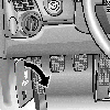
Remove the black molded panel from under the passenger dash by loosening the two plastic retaining screws with a regular screwdriver.
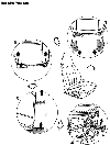
| Removing Front Seats | |||
|---|---|---|---|
 | |||
| No. | Procedure | Instructions | |
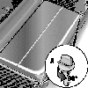
| 1 | Removing seat rail cover | Pull seat rail cover on front end of the right and left seat rails off in forward direction. | |
| 2 | Undoing seat screws at front | Move seat to its rear limit position and undo the front M10 x 28 Torx screws from the right and left seat rails using an E12 socket wrench insert. | |
| 3 | Undoing seat screws at rear | Move seat to its forward limit position and undo the rear M10 x 28 Torx screws from the right and left seat rails using an E12 socket wrench insert. | |
| 4 | Disconnecting electrical plug connection | Release plug connector locking device on the side and separate the plug connection. | |
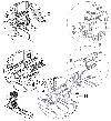
| Removing Center Console (Front Section) | |||
|---|---|---|---|
 | |||
| No. | Procedure | Instructions | |
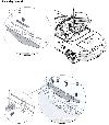
| 1 | Cover, front left | Unclip the front left cover -1- at the sides from clips -3-. | |
| 2 | Cover, front right | Unclip the front right cover -2- at the sides from clips -3-. | |
| 3 | Front trim | Unclip the front trim -12- towards the front (and disconnect the plug connections of the rocker switch if occupied). | |
| 4 | Left cover | Unclip the left cover -13- at the side and pull out to the rear from clips -3-. | |
| 5 | Right cover | Unclip the right cover -14- at the side and pull out to the rear from clips -3-. | |
| 6 | Center console (front section) | Undo fastening screws -5- and lift the front of the center console -15- off. | |
| 7 | Metal support bracket | Undo fastening nuts -17- and lift out the black metal support bracket -18-. | |
| 8 | Main console | Remove main console body. | |
| Access Under Gear Shift Mechanism | |
|---|---|
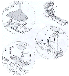
 | Undo fastening nuts that retain the gear shift mechanism in order to access the area underneath. |
